Build a Fun Countdown Timer Box for Free Meals at 08.08!
If you’ve ever wanted a portable, rechargeable countdown timer that rewards you with a special blink sequence when you stop right at 08.08 (to win a free meal in a restaurant!), you’re in the right place. In this project, we’ll build a neat little box that includes an Arduino with a 4-digit 7-segment display, all powered by a Li-ion battery and packaged in a 3D-printed enclosure.
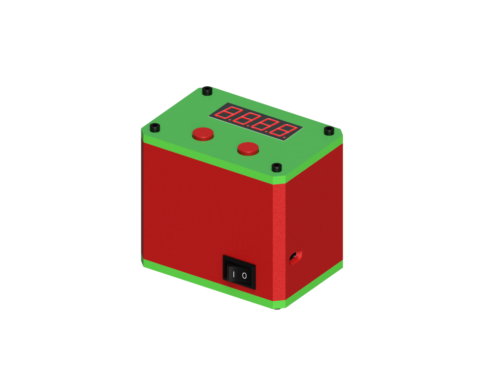
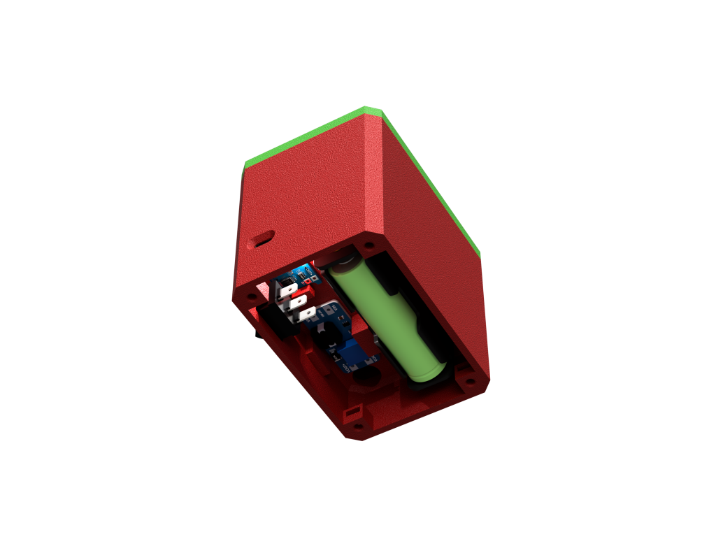
Table of Contents
- Project Overview
- Bill of Materials (BOM)
- Circuit and Wiring
- Arduino Code Walkthrough
- 3D-Printed Enclosure
- Assembly Steps
- Operation and Tips
- Conclusion
Project Overview
The main features of our Countdown Timer Box are:
- Rechargeable Power: A single 18650 Li-ion battery, charged via a TP4056 module, boosted to 10V (approximately) by an MT3608 step-up converter.
- Arduino Core: An Arduino Uno that handles timing and user input.
- Interactive Display: A 4-digit 7-segment LED for time readouts.
- Push Buttons: One to start/stop, another to reset.
- Special Easter Egg: Stopping the timer at 08.08 triggers a flashy blink sequence—perfect for marketing your restaurant’s free-meal challenge!
Important Note:
It is not recommended to use (i.e., power on and run) the device while the battery is being charged. The TP4056 expects a certain load environment, and having the timer running can cause unexpected battery stress or charging behavior.
Bill of Materials
You’ll need the following components to build this project:
- Arduino Uno
- 4-Digit 7-Segment LED Display (common anode or common cathode; code here is for a particular pin arrangement)
- 2× Push Button with Cap (12 mm diameter caps)
- 18650 Li-ion Battery
- 18650 Li-ion Battery Holder
- TP4056 Li-ion Charger Module (for safe charging via Micro-USB)
- MT3608 DC-DC Boost Converter (to step battery voltage up to ~5 V)
- On-Off Switch (13×20 mm, or adapt to whatever fits your enclosure)
- Enough Cable/Wires (for all connections)
- Soldering Equipment (soldering iron, solder, flux, etc.)
- 8× M3 Nuts
- 8× M3 × 12 mm Screws (for the enclosure)
- 3× M3 × 10 mm Screws (to mount the Arduino)
- Hot Glue (helps create a non-slip base and secure parts)
- 3D Printer
- PETG or PLA Filament (your choice, but PETG can be more durable)
Circuit and Wiring
Below is a quick outline of how to wire everything:
- Battery & TP4056
Place the 18650 battery in the battery holder.- Solder the holder leads to the TP4056 module’s
BAT+andBAT–. - The TP4056’s
IN+andIN–connect to a micro-USB jack, so you can charge the battery via USB.
- TP4056 & MT3608
- The TP4056 has output pins (
OUT+andOUT–) that feed the MT3608 input. - Adjust the MT3608’s output to around 10 V using its onboard potentiometer.
- The TP4056 has output pins (
- MT3608 → Arduino
- IMPORTANT: The MT3608 output should go to Arduino’s
VINpin rather than the 5 V pin. - Connect the MT3608 + output to Arduino VIN, and – output to Arduino GND.
- This setup goes through the Arduino’s onboard regulator circuitry at VIN.
- IMPORTANT: The MT3608 output should go to Arduino’s
- Arduino → 4-Digit Display
- Each segment pin (A, B, C, D, E, F, G, DP) is connected to a dedicated Arduino pin, as shown in the code.
- Each digit common pin is connected to pins 6, 9, 10, 11. (These pin assignments can vary if you adapt the code.)
- Push Buttons
- Start/Stop Button to Arduino digital pin 13 with
INPUT_PULLUP; other side to GND. - Reset Button to Arduino digital pin 12 with INPUT_PULLUP; other side to GND.
- Start/Stop Button to Arduino digital pin 13 with
- On-Off Switch
- Wire the switch in series between the MT3608 output and Arduino VIN, so you can flip the entire system on and off.
Because we’re drawing power from the MT3608 into VIN, it’s recommended to confirm your Arduino’s input voltage range. The VIN pin typically needs at least ~6 V for a stable 5 V regulator output. If your boost converter is only set for 5 V, the onboard regulator may drop some voltage, so you might want to boost it slightly above 6 V if stable. Alternatively, if you prefer a simpler approach, you can feed 5 V directly to the 5 V pin—but you specifically requested VIN, so be sure to adjust accordingly.
Arduino Code Walkthrough
Below is the full code. We’ll break it down line by line to show how it counts time, updates the display, and blinks when hitting 08.08.
#include <Arduino.h>  // Standard Arduino library

// Digit pins for the 4-digit display (left to right)
int digit_pin[] = {6, 9, 10, 11};

// Segment pins (A-G, plus decimal point DP)
int segA = 2;
int segB = 3;
int segC = 4;
int segD = 5;
int segE = A0;
int segF = 7;
int segG = 8;
int segDP = A1;  // Decimal point

// Display logic (depends on common-cathode or common-anode setup)
#define DIGIT_ON  LOW
#define DIGIT_OFF HIGH

#define SEGMENT_ON  HIGH
#define SEGMENT_OFF LOW

// Push button pins
int buttonStartStop = 13;
int buttonRestart   = 12;

// "timeCount" is how we measure time steps
// 0..1000 => 0.00..10.00 (i.e., up to 10 seconds)
int timeCount = 0;
bool isRunning = false;

// Variables to track elapsed time
unsigned long previousMillis = 0;  // last time we checked
unsigned long leftoverMs = 0;      // leftover milliseconds that haven't formed a 10ms chunk yet

// We'll increment every 10ms => 1000 increments = 10 seconds
#define TIMER_STEP_MS 10

void setup()
{
  // Set segment pins to OUTPUT
  pinMode(segA,  OUTPUT);
  pinMode(segB,  OUTPUT);
  pinMode(segC,  OUTPUT);
  pinMode(segD,  OUTPUT);
  pinMode(segE,  OUTPUT);
  pinMode(segF,  OUTPUT);
  pinMode(segG,  OUTPUT);
  pinMode(segDP, OUTPUT);

  // Set digit pins to OUTPUT
  for (int i = 0; i < 4; i++) {
    pinMode(digit_pin[i], OUTPUT);
  }

  // Configure buttons with pull-ups
  pinMode(buttonStartStop, INPUT_PULLUP);
  pinMode(buttonRestart,   INPUT_PULLUP);
}

void setSegmentsForNumber(int num, bool decimalOn)
{
  // First, ignore invalid digits
  if (num < 0 || num > 9) {
    return;
  }

  // Turn on the segments needed for this digit
  switch (num) {
    case 0:
      digitalWrite(segA, SEGMENT_ON);
      digitalWrite(segB, SEGMENT_ON);
      digitalWrite(segC, SEGMENT_ON);
      digitalWrite(segD, SEGMENT_ON);
      digitalWrite(segE, SEGMENT_ON);
      digitalWrite(segF, SEGMENT_ON);
      break;
    case 1:
      digitalWrite(segB, SEGMENT_ON);
      digitalWrite(segC, SEGMENT_ON);
      break;
    case 2:
      digitalWrite(segA, SEGMENT_ON);
      digitalWrite(segB, SEGMENT_ON);
      digitalWrite(segD, SEGMENT_ON);
      digitalWrite(segE, SEGMENT_ON);
      digitalWrite(segG, SEGMENT_ON);
      break;
    case 3:
      digitalWrite(segA, SEGMENT_ON);
      digitalWrite(segB, SEGMENT_ON);
      digitalWrite(segC, SEGMENT_ON);
      digitalWrite(segD, SEGMENT_ON);
      digitalWrite(segG, SEGMENT_ON);
      break;
    case 4:
      digitalWrite(segB, SEGMENT_ON);
      digitalWrite(segC, SEGMENT_ON);
      digitalWrite(segF, SEGMENT_ON);
      digitalWrite(segG, SEGMENT_ON);
      break;
    case 5:
      digitalWrite(segA, SEGMENT_ON);
      digitalWrite(segC, SEGMENT_ON);
      digitalWrite(segD, SEGMENT_ON);
      digitalWrite(segF, SEGMENT_ON);
      digitalWrite(segG, SEGMENT_ON);
      break;
    case 6:
      digitalWrite(segA, SEGMENT_ON);
      digitalWrite(segC, SEGMENT_ON);
      digitalWrite(segD, SEGMENT_ON);
      digitalWrite(segE, SEGMENT_ON);
      digitalWrite(segF, SEGMENT_ON);
      digitalWrite(segG, SEGMENT_ON);
      break;
    case 7:
      digitalWrite(segA, SEGMENT_ON);
      digitalWrite(segB, SEGMENT_ON);
      digitalWrite(segC, SEGMENT_ON);
      break;
    case 8:
      digitalWrite(segA, SEGMENT_ON);
      digitalWrite(segB, SEGMENT_ON);
      digitalWrite(segC, SEGMENT_ON);
      digitalWrite(segD, SEGMENT_ON);
      digitalWrite(segE, SEGMENT_ON);
      digitalWrite(segF, SEGMENT_ON);
      digitalWrite(segG, SEGMENT_ON);
      break;
    case 9:
      digitalWrite(segA, SEGMENT_ON);
      digitalWrite(segB, SEGMENT_ON);
      digitalWrite(segC, SEGMENT_ON);
      digitalWrite(segD, SEGMENT_ON);
      digitalWrite(segF, SEGMENT_ON);
      digitalWrite(segG, SEGMENT_ON);
      break;
  }

  // If decimalOn is true, light up the decimal point
  if (decimalOn) {
    digitalWrite(segDP, SEGMENT_ON);
  }
}

void turnAllDigitsOff()
{
  // Turn off all digits
  for (int i=0; i<4; i++) {
    digitalWrite(digit_pin[i], DIGIT_OFF);
  }
  // Turn off all segments
  digitalWrite(segA,  SEGMENT_OFF);
  digitalWrite(segB,  SEGMENT_OFF);
  digitalWrite(segC,  SEGMENT_OFF);
  digitalWrite(segD,  SEGMENT_OFF);
  digitalWrite(segE,  SEGMENT_OFF);
  digitalWrite(segF,  SEGMENT_OFF);
  digitalWrite(segG,  SEGMENT_OFF);
  digitalWrite(segDP, SEGMENT_OFF);
}

void displayOff(int durationMs)
{
  // Quick routine to blank the display for a set time
  unsigned long startTime = millis();
  while ((millis() - startTime) < (unsigned long)durationMs)
  {
    turnAllDigitsOff();
    delay(1);
  }
}

void loop()
{
  // --- Check Start/Stop button ---
  static bool lastStartStopState = HIGH;
  bool currentStartStop = digitalRead(buttonStartStop);

  if (lastStartStopState == HIGH && currentStartStop == LOW)
  {
    // The button was pressed => toggle the timer
    bool wasRunningBefore = isRunning;
    isRunning = !isRunning;

    // If we just started running, reset timing references
    if (!wasRunningBefore && isRunning) {
      previousMillis = millis();
      leftoverMs = 0;
    }

    // If we just stopped, check if timeCount == 808 => blink "08.08"
    if (wasRunningBefore && !isRunning && (timeCount == 808))
    {
      for(int i=0; i<10; i++)
      {
        // Show "08.08" for 200ms
        int dur = 200;
        unsigned long st = millis();
        while (millis() - st < (unsigned long)dur) {
          // Digit 0: '0'
          turnAllDigitsOff();
          setSegmentsForNumber(0, false);
          digitalWrite(digit_pin[0], DIGIT_ON);
          delay(2);

          // Digit 1: '8' + decimal
          turnAllDigitsOff();
          setSegmentsForNumber(8, true);
          digitalWrite(digit_pin[1], DIGIT_ON);
          delay(2);

          // Digit 2: '0'
          turnAllDigitsOff();
          setSegmentsForNumber(0, false);
          digitalWrite(digit_pin[2], DIGIT_ON);
          delay(2);

          // Digit 3: '8'
          turnAllDigitsOff();
          setSegmentsForNumber(8, false);
          digitalWrite(digit_pin[3], DIGIT_ON);
          delay(2);
        }
        // Turn off display for 200ms
        displayOff(200);
      }
    }
  }
  lastStartStopState = currentStartStop;

  // --- Check Reset button ---
  static bool lastRestartState = HIGH;
  bool currentRestart = digitalRead(buttonRestart);
  if (lastRestartState == HIGH && currentRestart == LOW)
  {
    // Reset the timer to 0
    timeCount = 0;
    leftoverMs = 0;
    previousMillis = millis();
  }
  lastRestartState = currentRestart;

  // --- Update timer if running ---
  if (isRunning && timeCount < 1000)
  {
    unsigned long now = millis();
    unsigned long elapsed = now - previousMillis;
    if (elapsed > 0)
    {
      previousMillis = now;
      leftoverMs += elapsed;

      // How many 10ms increments fit into leftoverMs?
      int increments = leftoverMs / TIMER_STEP_MS;
      if (increments > 0)
      {
        timeCount += increments;
        if (timeCount > 1000) timeCount = 1000; // cap at 10.00
        leftoverMs -= increments * TIMER_STEP_MS;
      }
    }
  }

  // --- Convert timeCount to digits (0.00..10.00) ---
  int integerPart  = (timeCount >= 1000) ? 10 : (timeCount / 100);
  int decimalPart  = (timeCount >= 1000) ? 0  : (timeCount % 100);

  int d0 = integerPart / 10;  // leftmost digit
  int d1 = integerPart % 10;
  int d2 = decimalPart / 10;
  int d3 = decimalPart % 10;

  // --- Display multiplexing ---
  // Digit 0
  turnAllDigitsOff();
  setSegmentsForNumber(d0, false);
  digitalWrite(digit_pin[0], DIGIT_ON);
  delay(2);

  // Digit 1 (with decimal)
  turnAllDigitsOff();
  setSegmentsForNumber(d1, true);
  digitalWrite(digit_pin[1], DIGIT_ON);
  delay(2);

  // Digit 2
  turnAllDigitsOff();
  setSegmentsForNumber(d2, false);
  digitalWrite(digit_pin[2], DIGIT_ON);
  delay(2);

  // Digit 3
  turnAllDigitsOff();
  setSegmentsForNumber(d3, false);
  digitalWrite(digit_pin[3], DIGIT_ON);
  delay(2);
}
3D-Printed Enclosure
- Download and Print: Grab the provided CAD/3D files (in STL format).
- Recommended Materials: PETG or PLA. PETG might be sturdier under heat, but PLA often prints more easily.
- Design Features:
- Mounting standoffs sized for 3× M3×10 mm screws to secure the Arduino.
- A top cutout for the 4-digit 7-segment display.
- Slots for push buttons and an on-off switch.
- A battery compartment to hold the 18650 cell securely.
- Potential openings for the micro-USB port (TP4056) if you want external access for charging.
Measure your exact modules and adapt any hole placements in the CAD if needed.
Assembly Steps
- Print the Enclosure
- Verify that the cutouts match your push buttons, on-off switch, and display dimensions.
- Mount the Battery Holder
- Secure it inside using hot glue or fast glue.
- Mount the Arduino
- Use 3× M3×10 mm screws to attach the Arduino Uno to the built-in standoffs.
- Ensure your Arduino’s terminals remain accessible.
- Solder and Wire
- Solder wires from the display to the Arduino’s corresponding pins (2, 3, 4, 5, A0, A1, 7, 8 for segments, 6, 9, 10, 11 for digit pins).
- Solder wires from the buttons to pins 12 and 13. The other sides of the buttons go to GND.
- Connect the MT3608 output to Arduino VIN and GND.
- Double-check all polarities before connecting your battery.
- On-Off Switch
- Place it in series on the line from MT3608 output to Arduino VIN so you can cut power completely.
- Insert Battery & TP4056
- Slide the 18650 battery into its holder.
- Position or secure the TP4056 so that the micro-USB input is accessible for charging.
- Close the Case
- Use M3×12 mm screws for the enclosure lid.
- Optionally add hot glue or rubber pads at the bottom to prevent slipping.
Operation and Tips
- Power On: Flip the on-off switch to supply power from the MT3608 to Arduino’s VIN.
- Start/Stop: Press the left button (or whichever you designated) to toggle the timer.
- Reset: Press the right button to reset the timer to 0.
- Target “08.08”: Try to stop exactly at 8.08 seconds. If you do, the display will blink “08.08” repeatedly—congratulations, you’ve won!
- Charging:
- Plug a micro-USB cable into the TP4056 for recharging.
- It is not recommended to use the device while it’s charging, as the charging circuit and boost converter can conflict under load. Let it charge, then unplug to operate.
Note: If you find the Arduino is not getting sufficient voltage through VIN (because the MT3608 is only at 5 V and there’s a drop across the onboard regulator), you may wish to boost the MT3608 output to around 6–7 V or feed the Arduino’s 5V pin directly (if you confirm the wiring). Just be mindful of your specific hardware requirements.
Conclusion
With this DIY Countdown Timer Box, you’ve:
- Learned the basics of multiplexing a 4-digit 7-segment display with Arduino.
- Explored Li-ion battery power using the TP4056 (charger) and MT3608 (boost converter), feeding the Arduino VIN pin.
- Built a compact 3D-printed enclosure that houses everything neatly.
- Created a fun, interactive timer game: Stop at 08.08 for a special surprise!
From here, you can expand the project—use a buzzer, extend the timer’s range, or incorporate Wi-Fi for a real-time scoreboard. Remember to charge safely and avoid running the system during charging. Happy making, and good luck hitting 08.08 for that free meal!
“Time you enjoy wasting was not wasted.” – John Lennon